Overview
In this lesson, you will learn how to control both the direction and speed of a small DC motor using an Arduino and the L293D motor driver chip.

The project uses a pot to control the speed of the motor and a push button to control the direction.
Parts
To build the project described in this lesson, you will need the following parts.
Part
Qty

Small 6V DC Motor 1

L293D IC 1
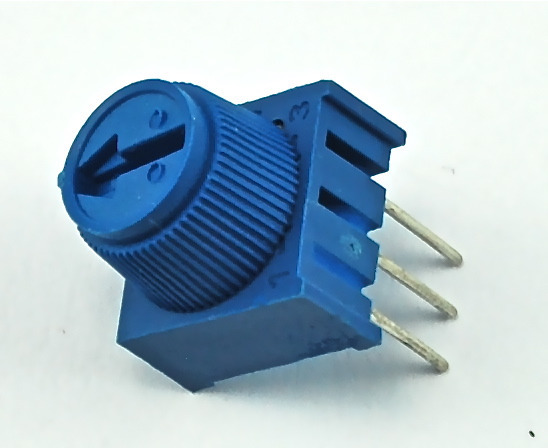
10 kΩ variable resistor (pot) 1

Tactile push switch 1

Half-size Breadboard 1

Arduino Uno R3 1

Jumper wire pack 1
An Experiment
Before we get the Arduino board to control the motor, we should experiment with the L293D motor control chip to get an idea how it works.
We can start by just using the Arduino to supply 5V to the motor.

Note which way the motor is spinning. You can do this by pinching the motor shaft between your fingers. Swap over the motor leads so that the motor lead that was going to +5V now goes to GND and vice-versa. The motor will turn in the opposite direction.
This gives us a clue as to how the L293D chip works. Its control pins allow us to do the equivalent of swapping over the motor terminals to reverse the direction of the motor.
Build up the breadboard as below. The Arduino is still just supplying power, but we can experiment manually with the control pins before we let the Arduino take over.

The three pins of L293D that we are interested in are Pin 1 (Enable), Pin 2 (In1) and Pin 7 (In2). These are attached to either 5V or GND using the purple, yellow and orange jumper wires.
As shown above, the motor should be turning on one direction, let's call that direction A.
If you move Pin 1 (Enable) to GND the motor will stop, no matter what you do with the control pins In1 and In2. Enable turns everything on and off. This makes it useful for using a PWM output to control the motor speed. Reconnect Pin 1 to 5V so that the motor starts again.
Now try moving In1 (pin 2, yellow) from 5V to GND. In1 and In2 are both now connected to GND, so again the motor will stop.
Moving In2 from GND to 5V will cause the motor to turn in the opposite direction (direction B).
Finally, moving In1 back to 5V so that both In1 and In2 are at 5V will again cause the motor to stop.
The effect of the pins In1 and In2 on the motor are summarized in the table below:
In1
In2
Motor
GND GNDStopped 5V GND Turns in Direction A GND 5V Turns in Direction B 5V 5V Stopped
Breadboard Layout
Now that we have got the hang of controlling the motor directly, we can let the Arduino manage the Enable, In1 and In2 pins.
When you build the breadboard, you need to ensure that the IC is the right way around. The notch should be towards the top of the breadboard.

Arduino Code
Load up the following sketch onto your Arduino.
int enablePin = 11;int in1Pin = 10;int in2Pin = 9;int switchPin = 7;int potPin = 0;void setup(){pinMode(in1Pin, OUTPUT);pinMode(in2Pin, OUTPUT);pinMode(enablePin, OUTPUT);pinMode(switchPin, INPUT_PULLUP);}void loop(){int speed = analogRead(potPin) / 4;boolean reverse = digitalRead(switchPin);setMotor(speed, reverse);}void setMotor(int speed, boolean reverse){analogWrite(enablePin, speed);digitalWrite(in1Pin, ! reverse);digitalWrite(in2Pin, reverse);}
Pins are defined and their modes set in the 'setup' function as normal.
In the loop function, a value for the motor speed is found by dividing the analog reading from the pot by 4.
The factor is 4 because the analog reading will be between 0 and 1023 and the analog output needs to be between 0 and 255.
If the button is pressed, the motor will run in forward, otherwise it will run in reverse. The value of the 'reverse' variable is just set to the value read from the switch pin. So, if the button is pressed, this will be False, otherwise it will be True.
The speed and reverse values are passed to a function called 'setMotor' that will set the appropriate pins on the driver chip to control the motor.void setMotor(int speed, boolean reverse)
{
analogWrite(enablePin, speed);
digitalWrite(in1Pin, ! reverse);
digitalWrite(in2Pin, reverse);
}
Firstly, the speed is set, by using an analogWrite to the enable pin. The enable pin of the L293 just turns the motor on or off irrespective of what the in1 and in2 pins of the L293 are set to.
To control the direction of the motor, the pins in1 and in2 must be set to opposite values.
If in1 is HIGH and in2 is LOW, the motor will spin one way, if on the other hand in1 is HIGH and in2 LOW then the motor will spin in the opposite direction.
The '!' command means 'not'. So the first digitalWrite command for in1 sets it to the opposite of whatever the value of 'reverse' is, so if reverse is HIGH it sets it to LOW and vice versa.
The second digitalWrite for 'in2' sets the pin to whatever the value of 'reverse' is. This means that it will always be the opposite of whatever in1 is.
L293D
This is a very useful chip. It can actually control two motors independently. We are just using half the chip in this lesson, most of the pins on the right hand side of the chip are for controlling a second motor.

A second motor would be attached between OUT3 and OUT4. You will also need three more control pins.
- EN2 is connected to a PWM enabled output pin on the Arduino
- IN3 and IN4 are connected to digital outputs on the Arduino


